-
Select
the text or line-art objects of which you want to change the color (using
 ).
Tip: If you want to select text or objects with the same color, you may better use the Select Similar Objects tool
).
Tip: If you want to select text or objects with the same color, you may better use the Select Similar Objects tool .
. -
Click the Fill and Stroke
 category and
make sure Fill
category and
make sure Fill  or
Stroke
or
Stroke  are
selected (depending on what you want to change).
are
selected (depending on what you want to change).
The Enfocus Inspector displays the current color settings of the selected objects.
-
Switch to the Stroke
Details subcategory:
- Select a Cap style and a
Join
style.
The cap style determines the appearance of the stroke at the end of a path.
The join style determines the appearance of the stroke at the corner points of a path.
Cap style Join style Icon Meaning Icon Meaning 
Butt cap 
Miter join 
Round cap 
Round join 
Projecting cap 
Bevel join - If you have selected a miter join style
,
set the Miter
Limit (Refer to Stroke attributes: Miter limit).
- In the Stroke Adjustment drop-down menu:
- To enable stroke adjustment, select
On.
With stroke adjustment enabled, all vertical and horizontal lines are rounded to an integer number of pixel thickness to give them the appearance of the same weight.
- To enable automatic stroke adjustment, select
Default.
When several strokes with the same line weight are rendered at low resolution, their rasterization may result in lines of different widths in device pixels (with a difference of one pixel at the most). This effect depends on how the exact position in real numbers of these strokes intersects with the device pixel grid. For a better visual result, automatic stroke adjustment can be enabled. This will automatically counteract the rasterization effects where needed, by slightly changing the line weight and coordinates, thus producing lines of uniform thickness in device pixels.
- To disable stroke adjustment, select
Off.
Vertical and horizontal lines are not adjusted. When rendered at low resolution, you may see small differences in width.
- To enable stroke adjustment, select
On.
- To make the line dashed
- Click the Dashed
Line button
 .
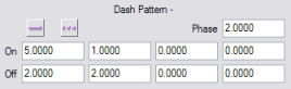
. - Specify the length of the dashes in the On boxes.
- Specify the gaps (space) between the dashes in the Off boxes.
- If necessary, move the dashes by specifying a Phase. The
phase indicates where the dash pattern should begin. For
example, in the example below:
- without phase, the first dash has a length of 5.0 (first value in the On field)
- with phase, the first dash has a length of 3.0 (first value in the On field minus the value specified for the phase)
The unit depends on the value set in the Preferences.
- Click the Dashed
Line button
Dashed line without phase 
Dashed line with phase 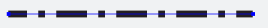

- Select a Cap style and a
Join
style.